Early Detection of Internal Inclusions and Shell Defects Using Magnetic Flux Leakage
Heiligenhaus, March 2022
- Inclusions get into the melt during the metallurgical process
- Some of these non-metallic particles remain in the steel products produced
- The purity of steel is defined by the quantity, particle size and spatial distribution of these non-metallic particles remaining in the strip
- The innovative Inclusion Detection System (IDS) of IMS detects those defects continuously in a non-contact and non-destructive detection technique
The demands placed on steel as a material are growing continuously due to the ongoing development of the material and its processing methods. This also applies to the purity of the steel.
As a result, exact control of the production processes is essential for the production of high-quality end products in order to provide the finishing industry with flawless starting materials with homogeneous material structures. To be able to ensure this, it is important to determine various parameters over the entire length of the strip.
A selective material inspection at the ends of the strip is not sufficient to reliably prevent material defects in the end products and possible damage to tools in the downstream forming processes.
Task
In steel production and the subsequent casting process, inclusions get into the melt during the metallurgical process. Some of these non-metallic particles remain in the steel products produced.
In the subsequent rolling processes, these internal defects are not rolled out of the steel, but take on an elongated shape due to the deformation of the material. The purity of steel is defined by the quantity, particle size and spatial distribution of these non-metallic particles remaining in the strip.
If these do not appear as open defects on the surface of the material, they cannot be detected with conventional optical measuring systems.
In order to be able to reliably detect such internal inclusions and shell defects, IMS was tasked specifically to develop a measuring system for continuous non-contact and non-destructive detection of the defects described during the ongoing production process.
Technical Principle of the Inclusion Detection System (IDS)
If there are local areas in the material with significantly lower permeability, caused by non-metallic inclusions, cracks and indentations on the surface, the magnetic resistance increases at this point. A part of the magnetic flux is thus forced to the surface of the material. The difference between the relative permeability of the material and the surrounding air results in pronounced magnetic refraction. The extent of the stray field emerging from the material surface is therefore significantly greater than the causal defect, which enables its detection.
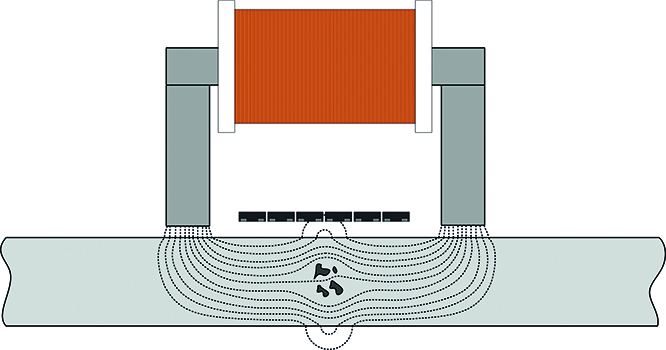
Figure 1: Schematic illustration of the magnetic field profile in the case of an internal inclusion (source: IMS)
The IDS flux leakage detection system developed offers the functionality of a complete flux leakage test during ongoing production operation. Electromagnets are used to magnetise the material. Their power can be adapted to the properties, structure and geometry of the material being inspected and can be switched off for maintenance and cleaning purposes. The stray fields are detected by means of GMR sensors.
The sensors used are GMR differential sensors (gradiometers). They consist of 4 individual GMR sensors that are connected in the form of a Wheatstone measuring bridge. Two of these sensors each are linked spatially. A differential signal is formed in dependence on the difference in magnetic field strength between the two sensitive areas.
The use of gradiometers enables a significantly higher amplification compared to absolute sensors (magnetometers) as external fields have no influence on the sensor signal. This means that particularly small local magnetic field inhomogeneities can be detected.
In the IDS measuring system, the material is magnetised transversely to rolling direction. This direction of magnetisation was chosen on the basis of laboratory measurements with artificial defects. These defects were defined as through holes of different diameters as well as grooves with a length of 1 mm, a width of 100 µm and variable depth.
The internal inclusions occurring in cold-rolled strip normally take on elongated shapes due to the strong deformation. Grooves, therefore, correspond most closely to the defects that actually occur.
For holes, which correspond to compact defects, approximately equivalent results were obtained with all magnetisation directions. For grooves, significantly better signal-to-noise ratios were obtained with magnetisation transverse to the rolling direction. This can easily be explained by the larger defect cross-section in this direction.
Magnetisation at a 45° angle to rolling direction is not a compromise, as this worsens the signal-to-noise ratio for compact defects compared to parallel magnetisation, without improving the signal-to-noise ratio for elongated defects.
With magnetisation transverse to the rolling direction, the maximum yoke width of the magnet is limited. Due to a suitable magnetic field homogeneity, the yoke width was chosen so that a 48 mm wide area is measured in each case. Consequently, multiple magnets are necessary in order to cover the different material widths. Since no measurement is possible in the area of the pole shoes of the magnets, the sensor modules are arranged in two rows for continuous coverage.
Structure of a Sensor Block
One magnet and the sensor line inside each magnet were combined to form a compact sensor module. This guarantees easy maintenance, repair and scalability of the measuring system.
A sensor module contains the sensors, the amplification and filtering of the sensor signals, AD converters as well as the control of the electromagnet and stabilised voltage supplies. The sensor modules are installed quickly and reproducibly on the measuring system using quick-release clamps in conjunction with fitting screws. Mechanical adjustment is not necessary thanks to the precise manufacture and assembly of the individual module components.
The GMR sensors are encapsulated into a sensor block within a protective and stabilising aluminium frame. This hinders adhesion of dirt and provides protection against mechanical damage.
The sensor modules comply with protection class IP 64, which enables direct use in harsh environments. The modular design ensures easy replacement of the sensor block without adjustment work.
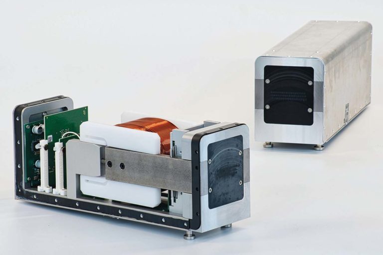
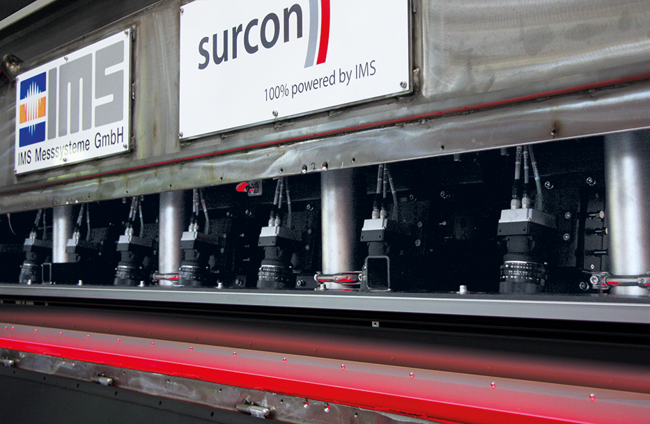
Figure 2: Sensor module (source: IMS)
A sensor module has an outer width of 95 mm, which allows two sensor module rows to cover the material without gaps. Each sensor module contains 48 GMR differential sensors in the centre of the magnet. The distance between the sensors transversely to rolling direction is 1 mm. This is advantageous as the size of the stray fields of the smallest defects is also above 1 mm.
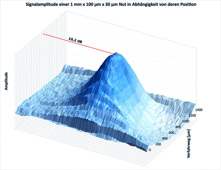
Figure 3: Signal amplitude of a 1 mm x 100 µm x 30 µm groove depending on its position (source: IMS)
The resolution of such a sensor arrangement thus suffices to detect even the smallest defects. At the same time, the sensors used are more sensitive than smaller sensors with higher spatial resolution. This means that particularly weak signals of small defects can be detected better. The defects detected by a sensor are determined via the signal amplitude.

Figure 4: Signal amplitude of different defects depending on their volume
The overall system is structured hierarchically. The individual levels work on a task basis and are interconnected via fast network technology. The sensor signals are converted from analogue to digital with a sampling rate of up to 187.5 kHz at a resolution of 15 bits. Length-dependent scanning takes place with a constant longitudinal resolution (rolling direction) of 0.1 mm.
The digitised sensor signals from up to eight sensor modules are fed to a common Gig-E hub and converted to the Gig-E camera standard. The Gig-E hubs are connected to a camera computer. This camera computer has the following tasks:
⋅ Signal pre-processing
⋅ Detection of defects
⋅ Feature computation
⋅ Classifikation
⋅ Control and adjustment of the sensor modules
The database server is superimposed on this camera computer. The database server stores the defect images and contains the production and training database. Visualisation of the defects as well as the connection to the customer database is effected via the database server.

Figure 5: Hardware structure
Technical Production Design
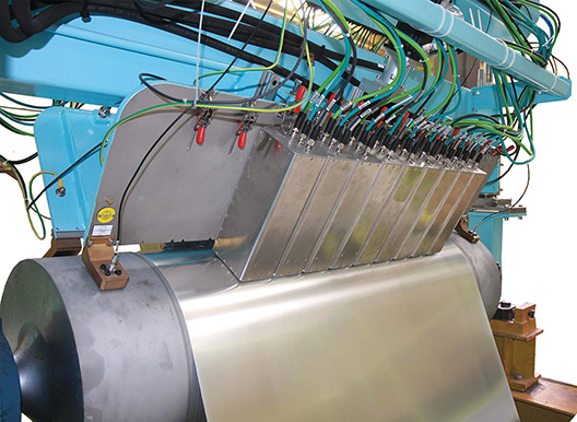
After extensive laboratory tests and a successful pilot phase, the market-ready measuring system with 28 sensor modules (maximum material width 1,344 mm) was installed in a tinning line and commissioned successfully.
Product Data
Strip thickness
Strip width
Strip speed
Measuring distance
Measuring Accuracy
Detectable defect size (substitute defect)
Distance influence
Reproducibility
0.1 – 0.6 mm (max. 1 mm)
600 – 1,250 mm (measuring width 1,344 mm)
max. 1,000m m/min at full resolution
> 0,5 mm
Hole: 70 µm diameter, groove: 10 µm deep, 100 µm wide, 1,000 µm long in strip 250 µm thick
The minimum defect size must be determined depending on the application
1 dB / 100 µm
>98 %
The measurement takes place on a deflection roller with two rows of sensor modules. The position of the sensor modules can be adjusted to different material thicknesses with the help of servo motors.
To ensure mechanical stability, the sensor module rows and their carriers are kept at a constant temperature by means of water. The water cooling also serves to dissipate the waste heat of the sensor modules.
The measuring system also has a pneumatic drive to move the sensor rows on and off the belt surface completely. The drive is activated automatically in case of danger of collision with the material for quick lifting of the measuring system from the strip surface.
The distance of the sensor modules to the strip surface is monitored permanently by three capacitive distance sensors per sensor module row. As an additional safety device, the measuring system has an optical wrinkle detector. This is a laser light barrier which is installed in the strip run 10-20 m in front of the measuring point. In case of wrinkles in the material, the sensor rows are swivelled away.
The measuring system can be moved to a park position outside the system. In this position, the sensors are adjusted automatically and maintenance work can be carried out while the line is running. During the automatic adjustment, all sensors are standardised to a defined magnetic sensitivity and defective sensors are detected.
Measurement Results
The following figures show the raw signals of artificial defects: a hole with a diameter of 100 µm and surface grooves with a length of 1 mm, a width of 100 µm and depths of 30 µm and 10 µm respectively in 200 µm thick steel strip at a measuring distance of 500 µm and a speed of 500 m/min.

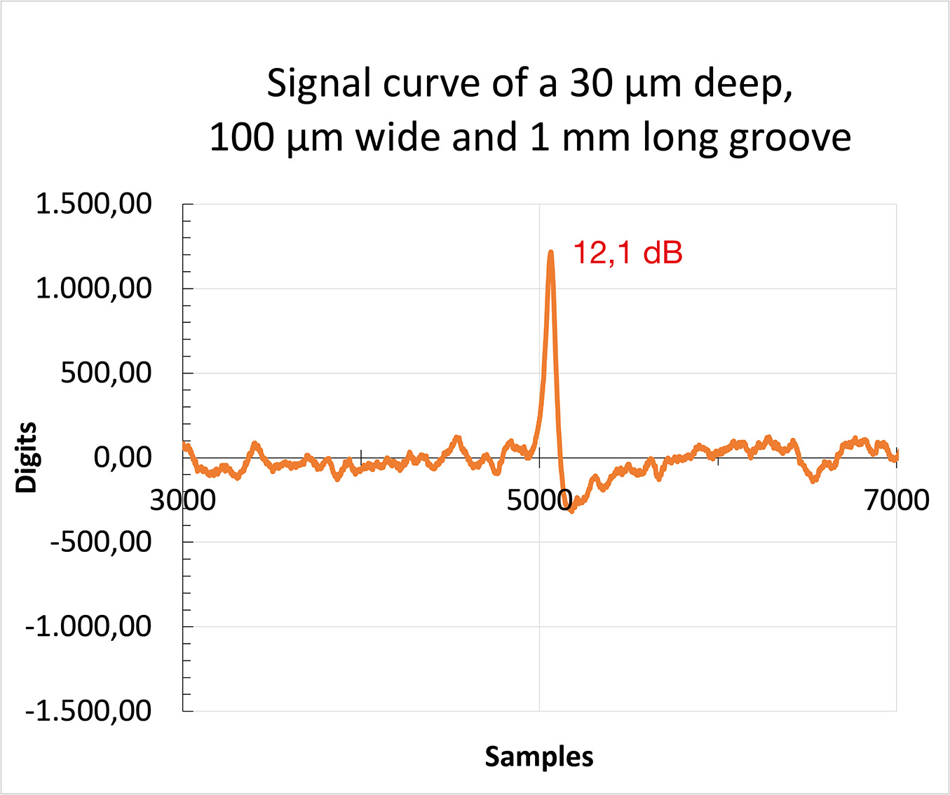
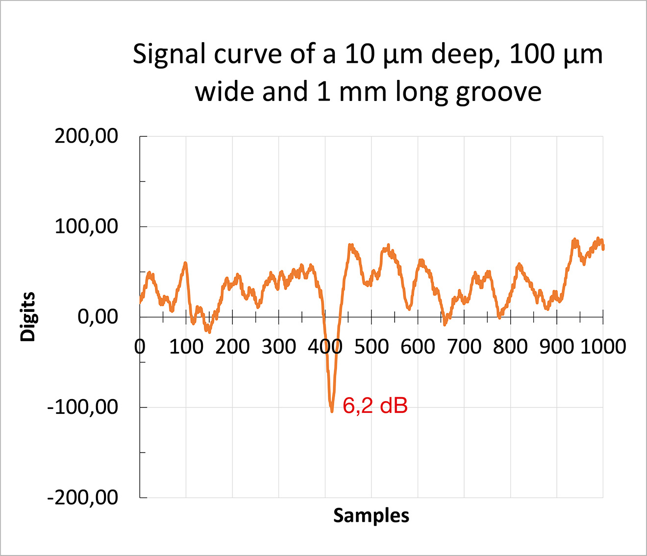
Figures 6-8: Signal profiles of a 100 μm hole and 1 mm long grooves, 10 μm and 30 μm deep, 100 μm wide (source: IMS)
Surface defects on the opposite side of the material to the measuring system can also be detected.
Figure 9 shows the raw signal of grooves measuring 1 mm x 100 µm x 25 µm in 200 µm thick steel strip. The first groove is on the side of the material facing the measuring system, the second on the opposite side. As can be seen in the figure, the defect position within the material has only little influence on the signal-to-noise ratio of defect signals.
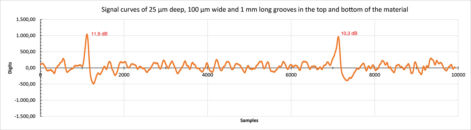
Figure 9: Groove signal profile, top and bottom strip side
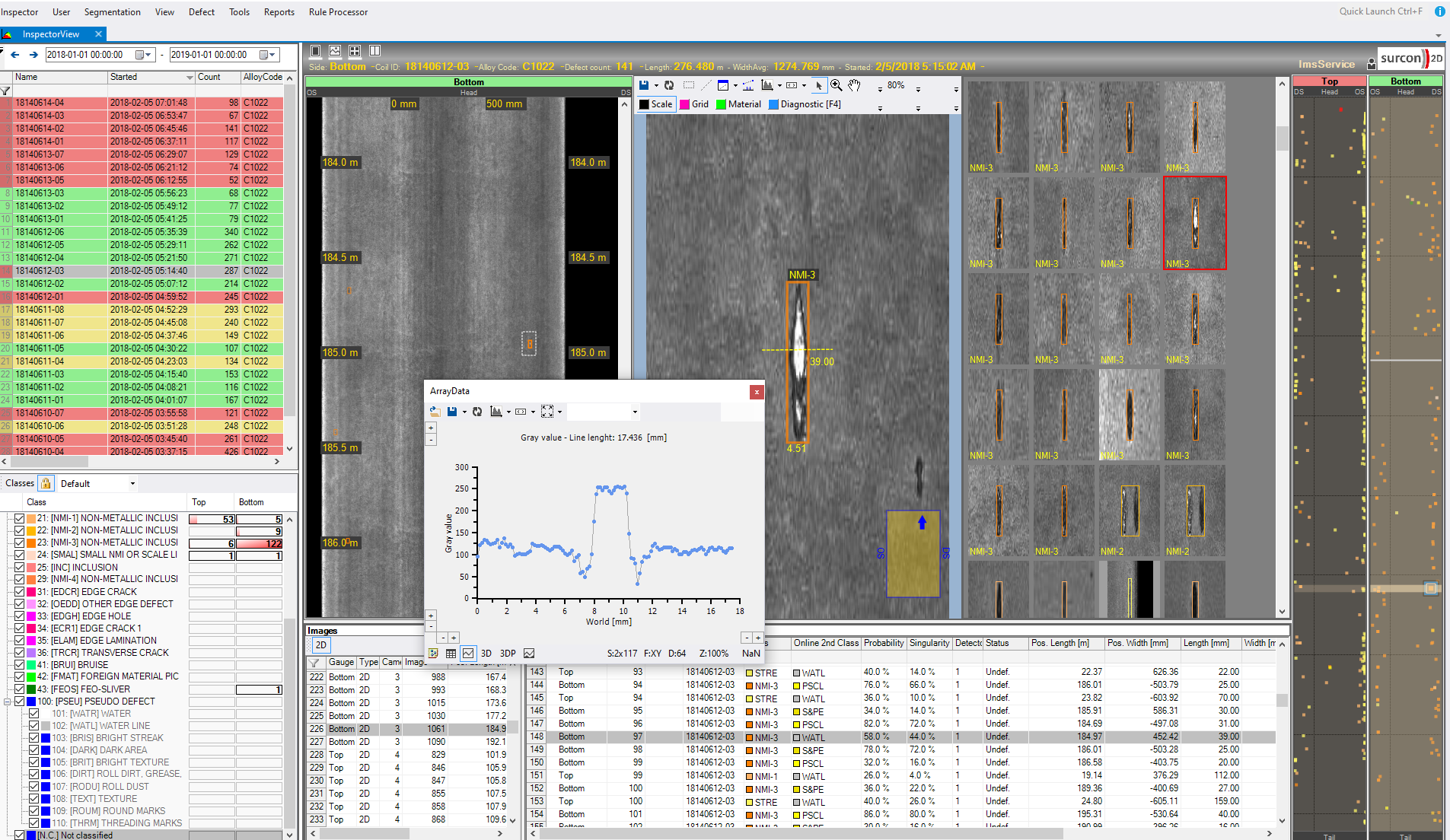
Operational Measurement
The internal inclusions measured are evaluated as follows:
1) Based on defect size (amplitude/volume)
2) Based on classification (e.g. shells, cracks, overlaps, M-defects, scratches, indentations)
Some inclusions detected were located precisely in the laboratory by means of magnetic particle inspection and examined subsequently by making 3 sections each transverse to the rolling direction.
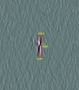
Figure 10: IDS image of defect

Figure 11: Magnetic particle image of defect
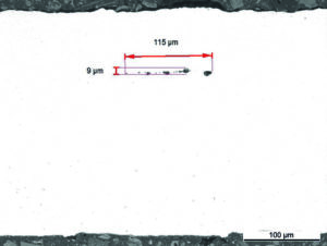
Figure 12: 1st section, defect

Figure 13: 2nd section, defect
Picture 14: 3rd section, defect
Summary
Using high-quality measuring electronics and advanced image processing, IMS Messsysteme GmbH has developed a high-resolution measuring system for internal defects and external material damage in the form of its Inclusion Detection System (IDS).
The market-ready IDS is available to cold strip rolling mills for comprehensive evaluation of purity. The maximum strip thickness at full sensitivity is 1 mm. The inspection system is scalable for any strip width and can be adapted individually to customer specifications.
The image processing with feature calculation and classification used distinguishes the defects based on their size and type. The classification is adapted to the respective material and the customer specification.
Use of an IMS Inclusion Detection System helps to avoid delivery of defective material and ensures perfect product quality for the end customer. In addition, the measurement results are used to optimise the pre-material stages. By improving quality and output, resources are conserved and costs reduced.


